• Mid fuse lower structure
    Fuselage Section 26
    Apr 30, 2022

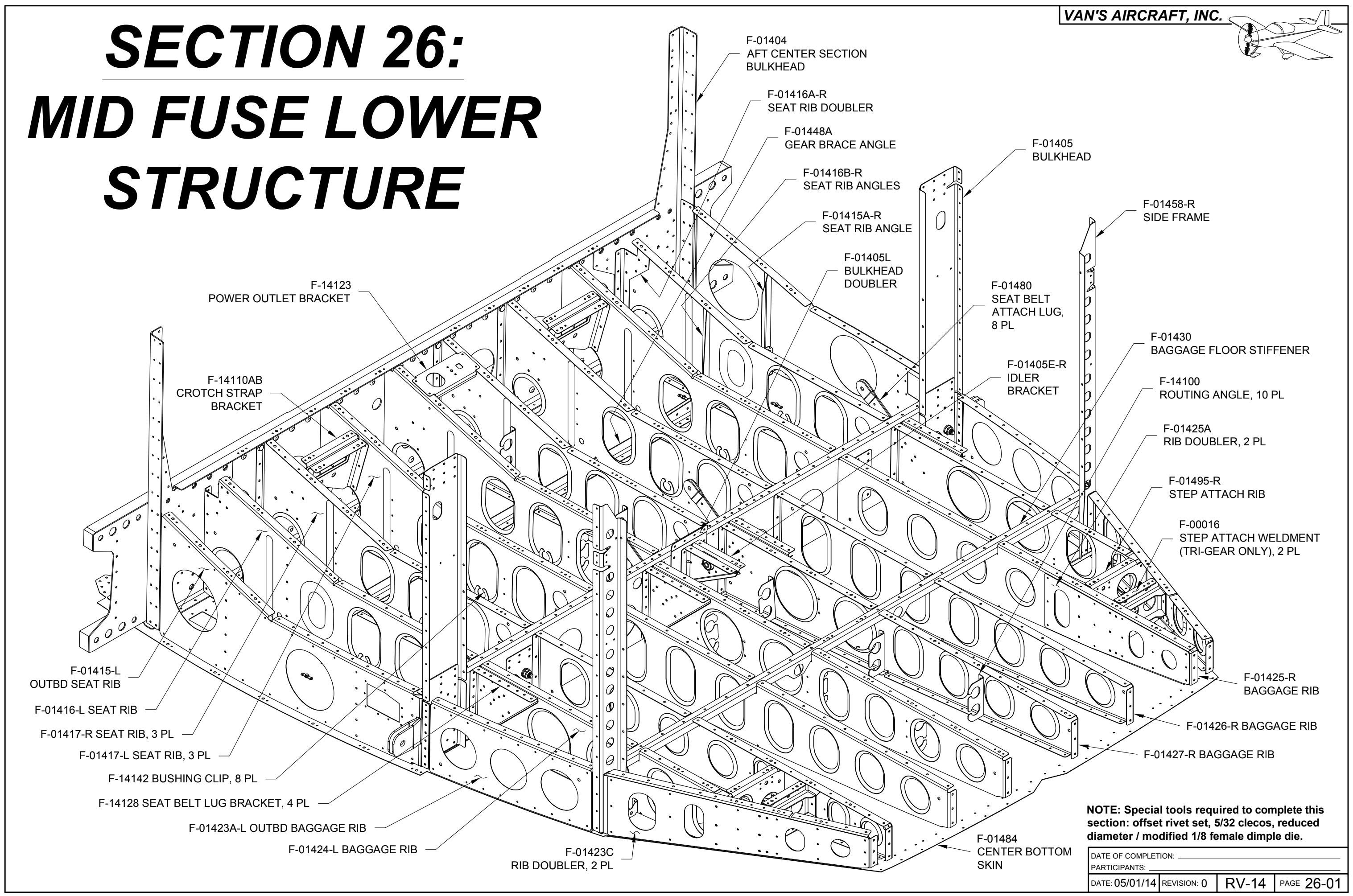
    I've found that spending the time upfront to make sure that all flanges are at their proper angles, and that all fluting is performed such that hole patterns line up exactly without preload has saved a ton of time dealing with it after parts start getting assembled. Here, the outermost ribs follow a curve to follow the contour of the fuselage that needs to be carefully fluted to match the hole pattern in the bottom skin.

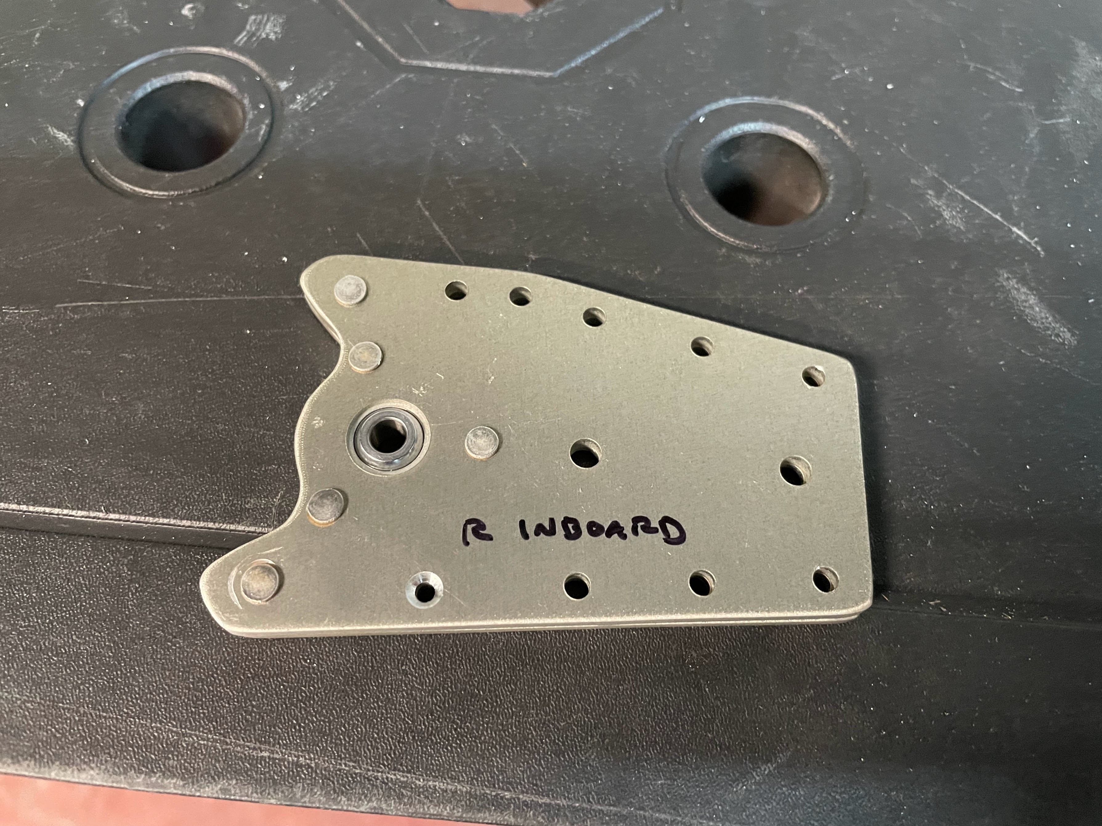
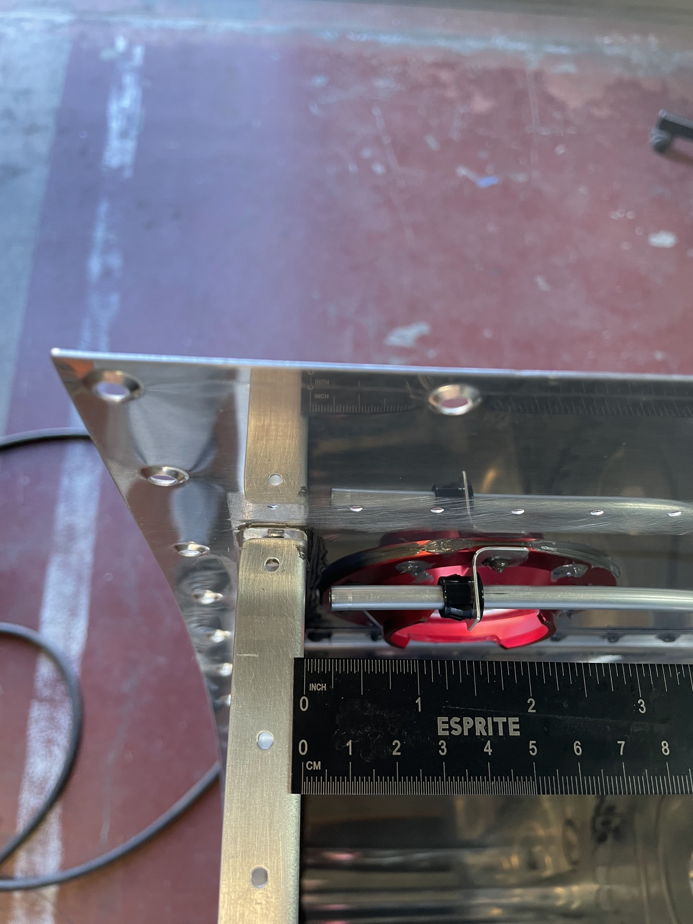
    The idler bracket gave me some trouble, given that a 45 degree bend has to be made on the diagonal edges very close to the edge on relatively thick material. A hand seamer was simply unable to make this bend without either badly scarring the material, or resulting in a bed that is not at all sharp. Instead I fabricated a bracket out of angle aluminum as a backing plate, clamped the assembly down to a table, and used a combination of the hand seamer as well as hammering the edge to form the bend.

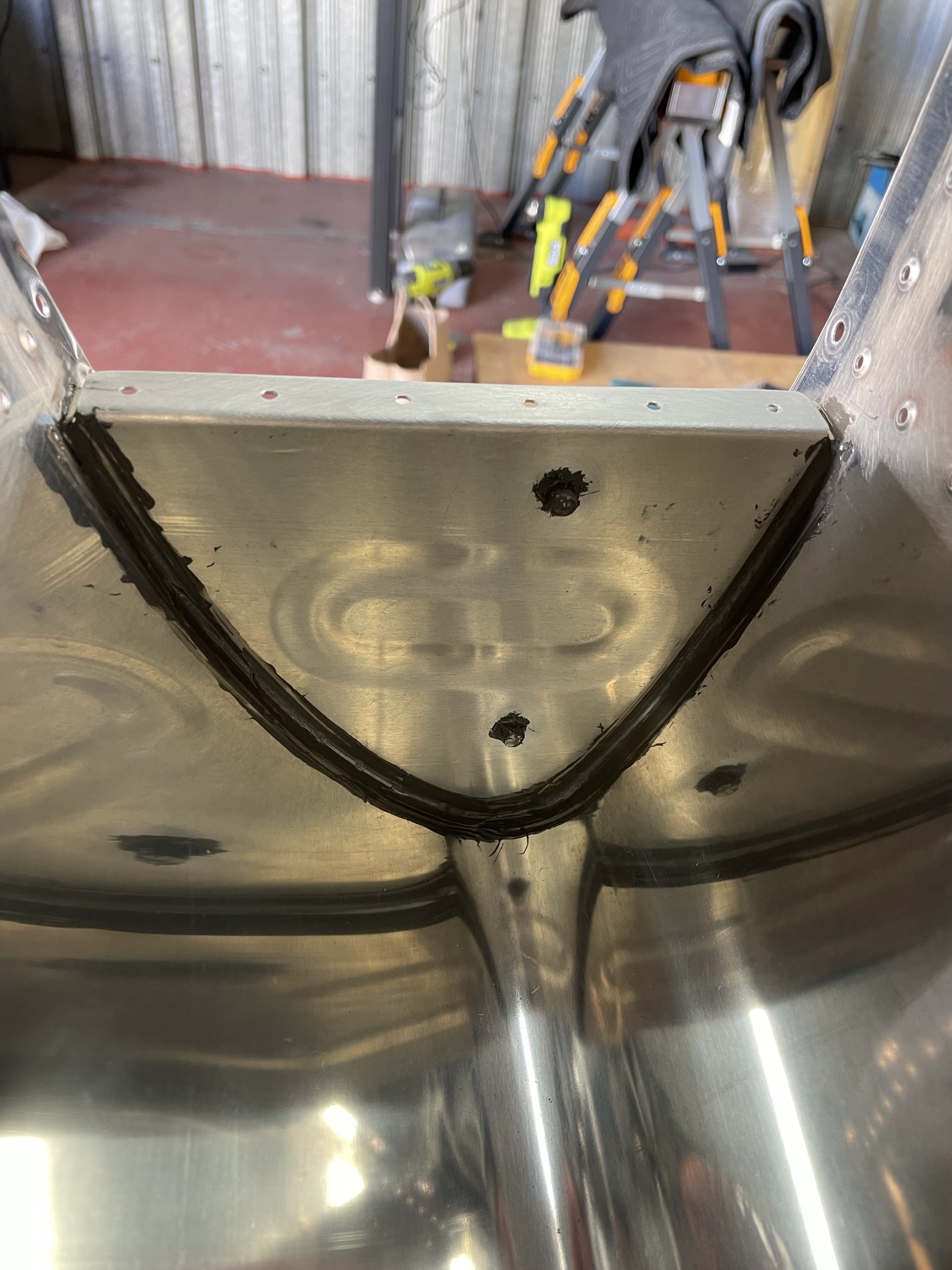
    Next is priming, dimpling, and riveting on various doublers and stiffeners to the bottom skins. Everything here was back riveted and straight forward.

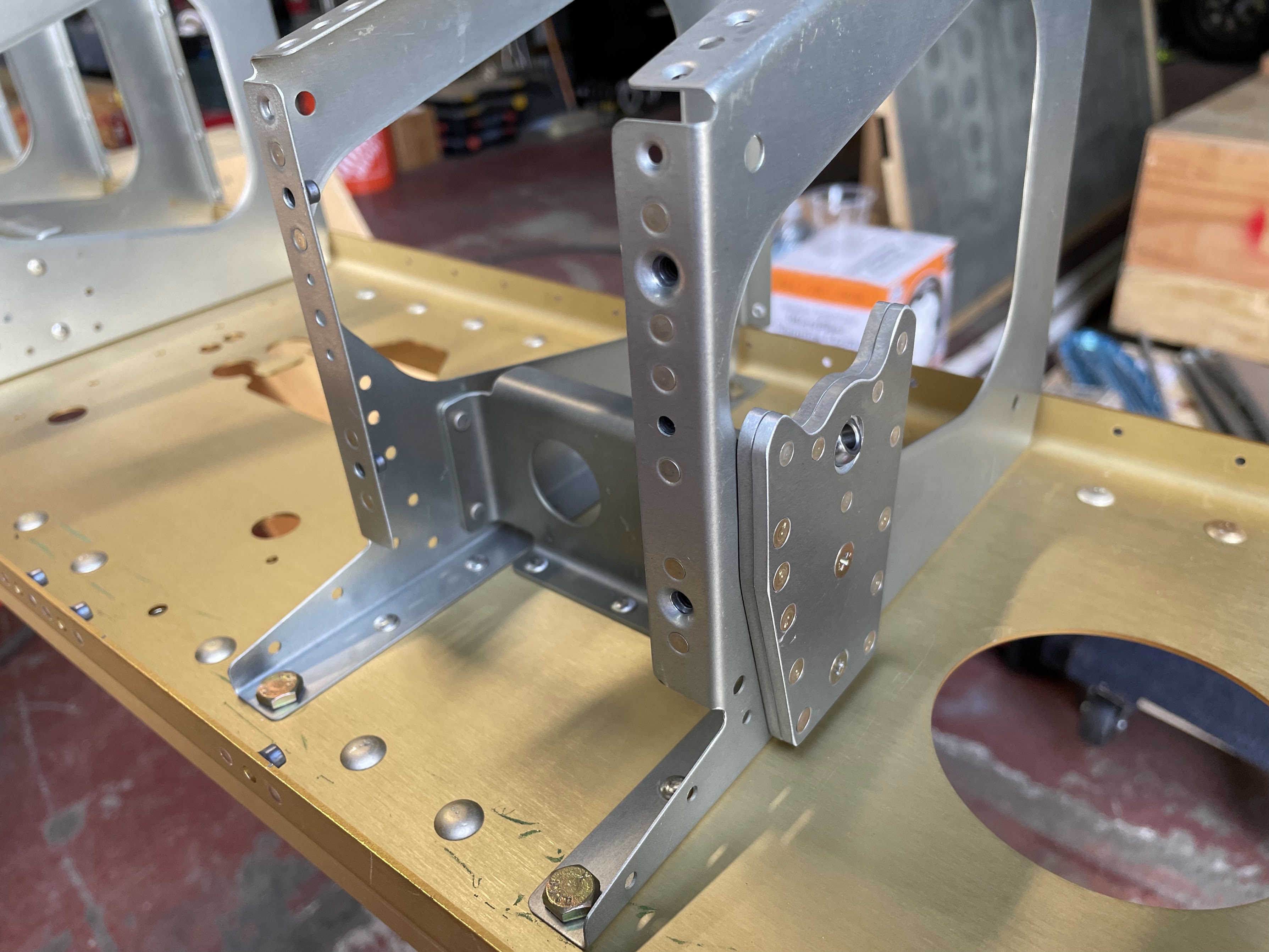
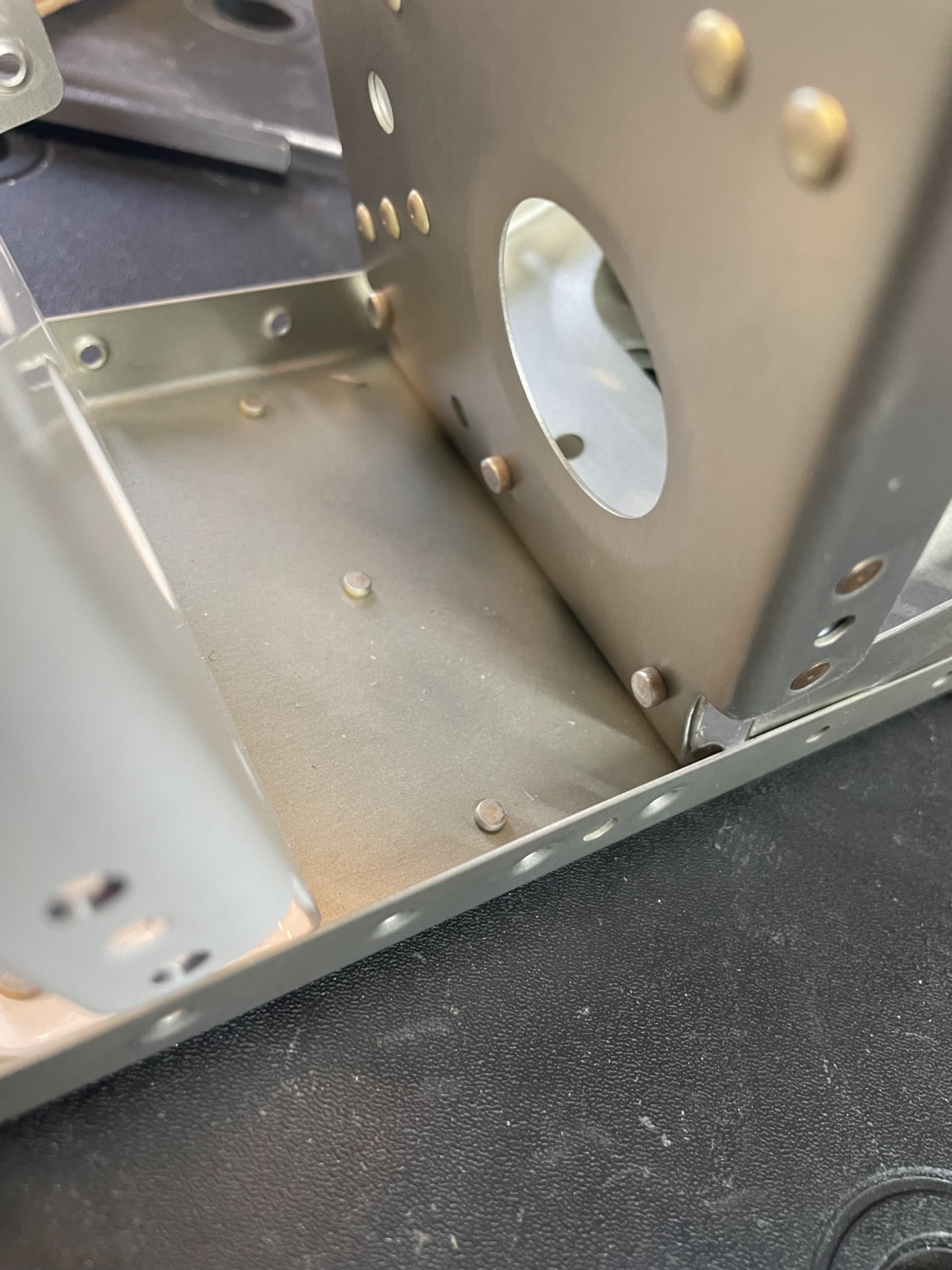
    The step brackets are attached at an angle, and were a bit of a challenge to set some of the rivets, particularly the AD4- rivets in the corner. Here the tiny tungsten bar with angled sides came in handy, but still a challenge to drive and buck.

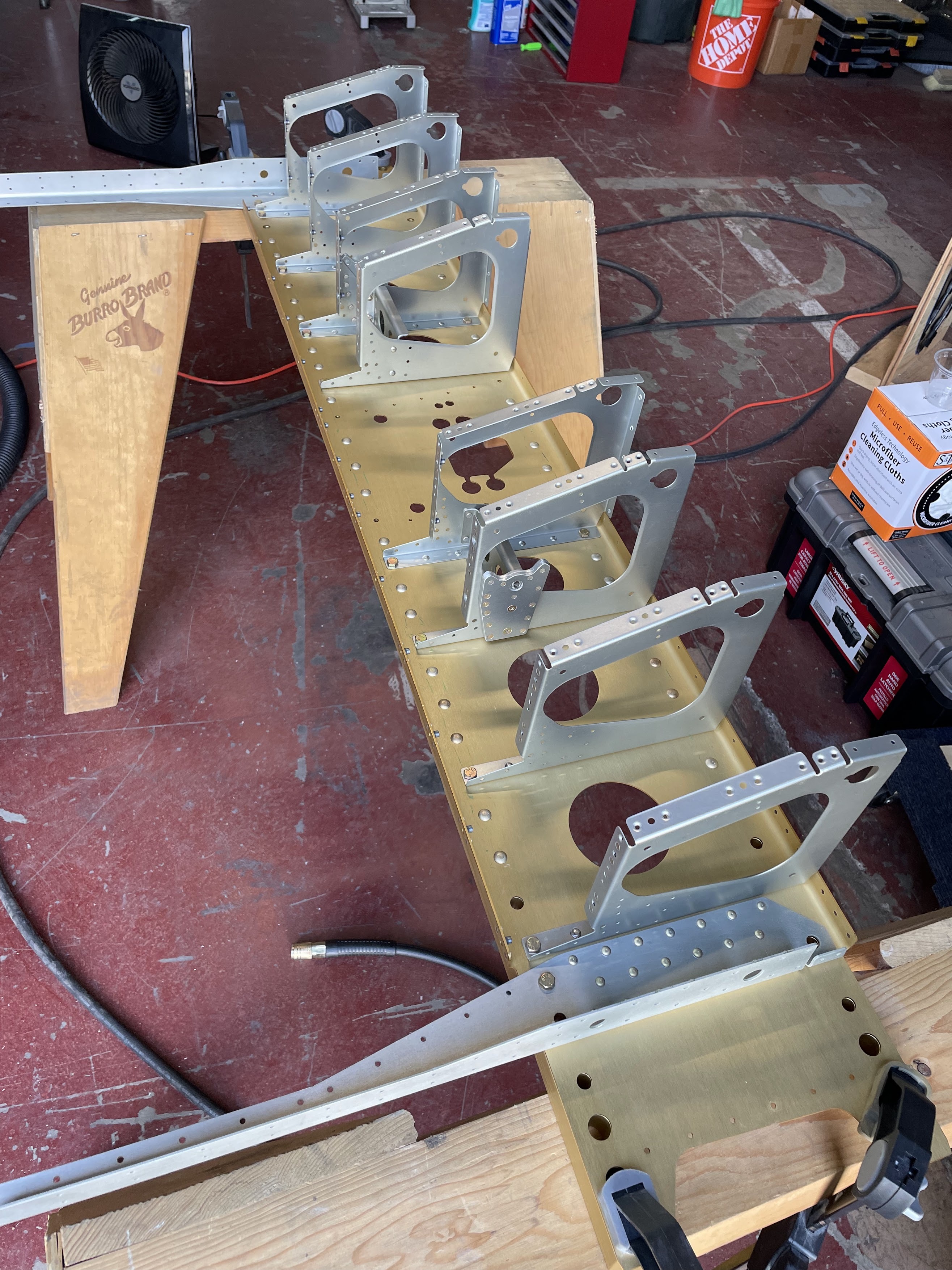
    The mid-rib gear brackets are each attached with 3 AD 4- rivets that need to be aligned perpendicular to the bottom skin. I used a rafter square here, and checked/adjusted after every rivet.

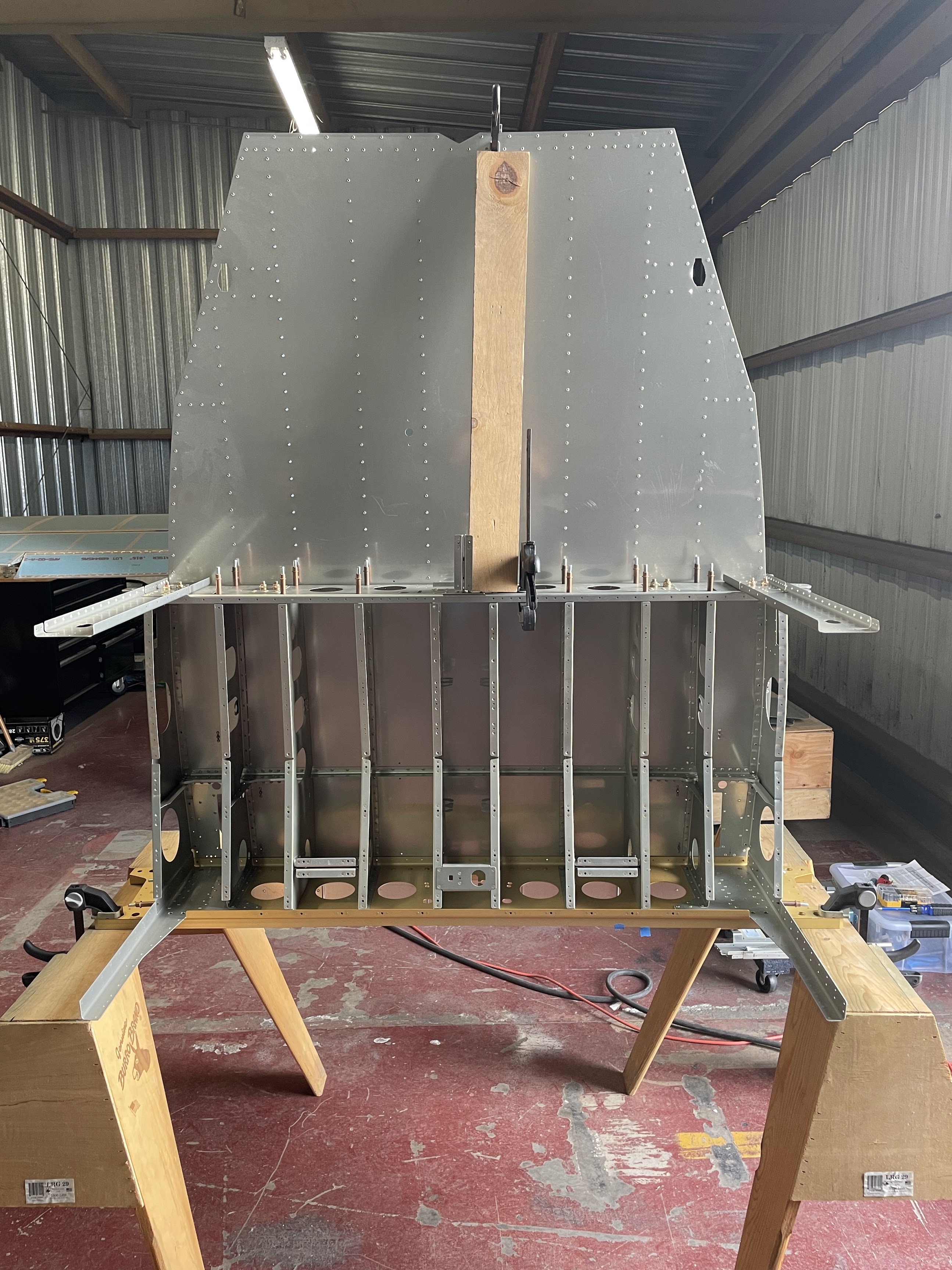
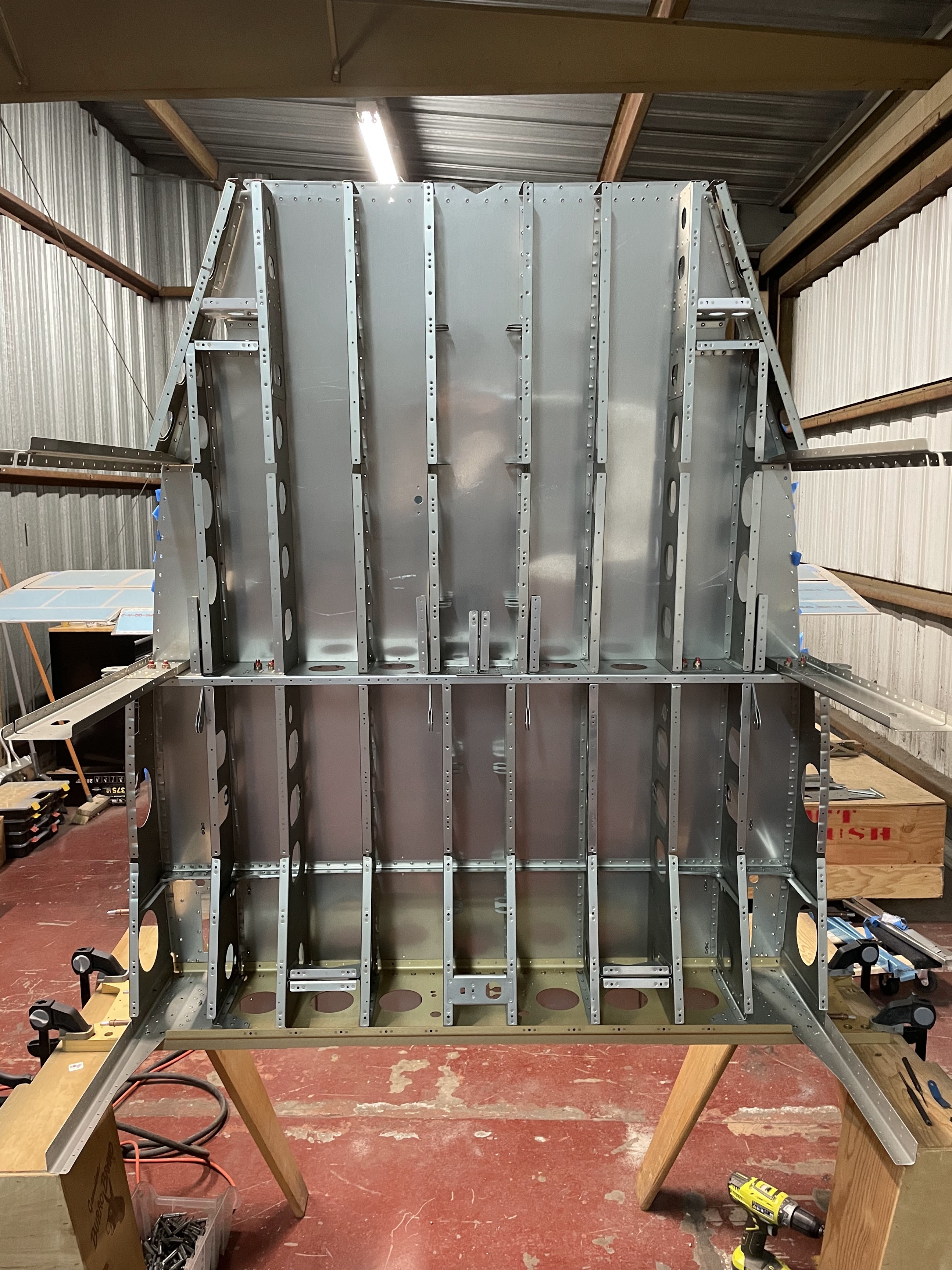
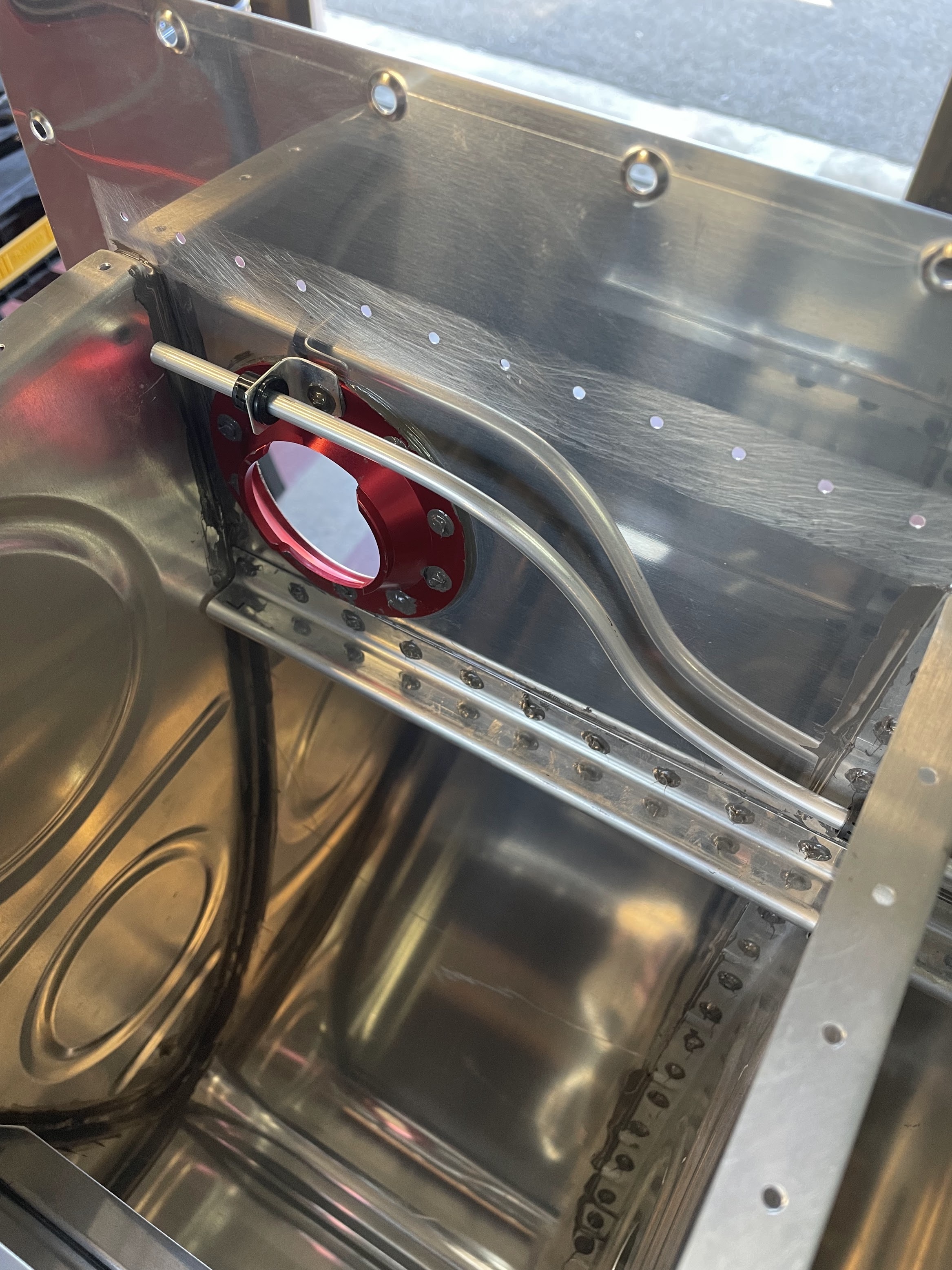
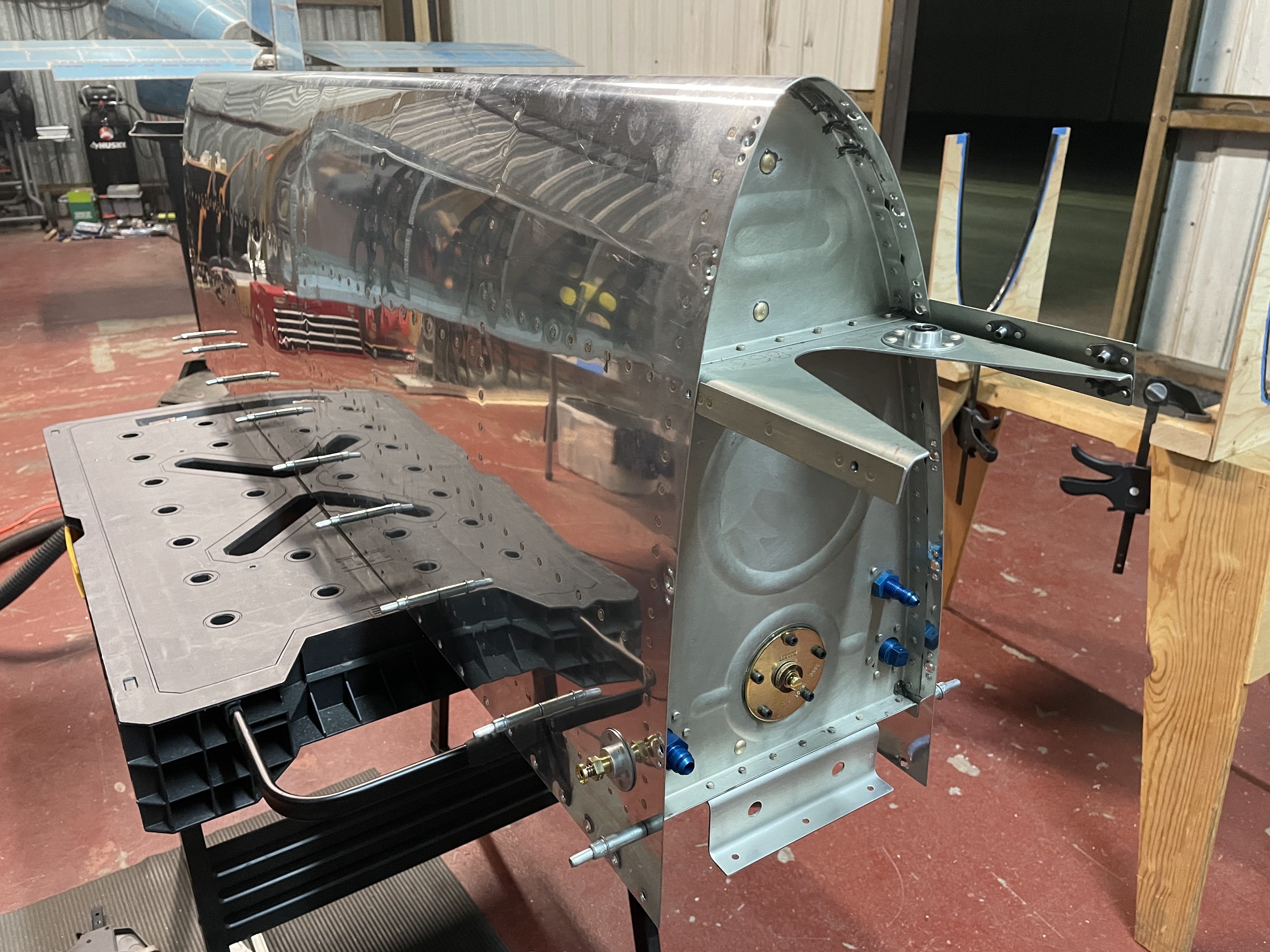
    When starting to attach the aft ribs, it was easier to set the whole assembly vertically by clamping the spar flat against a table or pair of sawhorses. This made the aft skin fairly floppy to start as there was nothing to support it, so I just clamped a piece of wood to it to keep it flat while attaching ribs. This put everything in a fairly accessible position to rivet. I ended up doing much of this single-handed, but the rivets near the center definitely require two people.


  • Fwd mid fuse bulkheads
    Fuselage Section 25
    Apr 10, 2022

    Finally get to break out the pretty gold anodized center spar sections! Everything here was pretty basic given that there was easy access to rivet components onto the spar. The only place it got a bit tight is in trying to tighten and torque the bolts for the bearing bracket. There's a screw head on the bolt, and not a lot of room to squeeze in there unless you have a stubby screwdriver.

    Lastly for reaming the bolt holes for the rear spar brackets, I drilled a block of wood with the final size dimensions using a drill press and clamped it to the part as a guide to keep the reamer perpendicular.


  • Completing fuel tanks
    Fuel Tank Section 18 Wing
    Apr 3, 2022

    Closing up the fuel tanks went relatively smoothly after a little planning, and watching over the video that Vans produced several times. I found that I could only do about 2 ribs in a row to stay within the working period of the proseal, which included mixing the proseal, apply it to a rib, get the rib seated and cleco'd into the tank, rivet the rib, and doing the final fillet / smoothing around edges, and sealing off the shop heads.

    There were two places in particular that gave me problems that I would probably have done differently if I were to do it again. The first was the inboard external ribs that butt against the tank attach bracket. This area has a lot of mating parts, and on both tanks I noticed a small leak due to insufficient sealant between the skin and the bracket flange. Simply tracing a heavy fillet between the skin and the mating parts was insufficient for sealing this area. I ended up having to drill out many of the rivets in this area, and get creative trying to press sealant under the skin to get it sealed. In hindsight I would have just slathered all the flanges in sealant and dealt with the resulting mess. The other problem area was the float sensor. This is attached with 5 screws, and I'm still unsure if I need to seal the threads of the screws, or can seal it at the head - although this can easily be addressed afterwards and doesn't need any disassembly of the tank.

    Getting the back bulkhead in place went a bit better than expected. Using the semco gun helped quite a lot here, and laying an even continuous bead along the entire flange was actually quite easy.

    Lastly the nervous moment of leak testing the tanks. It took several iterations of trying to tie the balloon to the fitting in a way that didn't leak right where the balloon attaches. I found that a tight rubber band seemed to do the trick. I did find a tiny pinhole at the fuel drain fitting in one tank, and a small leak in both tanks in the exact same location at the point the tank attach brackets mate with the skin. Everything was fixed, and both tanks were able to hold pressure without any noticeable change in the balloon size for at least 2 weeks. Fingers crossed that means they're leak free and robust.


  • Starting fuel tanks
    Fuel Tank Section 18 Wing
    Nov 25, 2021

    I had been putting off working on the fuel tanks for the better part of 6 months, and coincidentally have had a container of proseal sitting in the fridge for about 6 months. The impeding expiration of the sealant has created the necessary inspiration to get this one finished.

    Vans has created a wonderful walkthrough for tank construction here that has helped a lot with visualizing many of the steps as well as a bunch of good tips on technique.

    First step was all the standard material prep. I took extra care on getting all the flanges at 90-degrees, and fluting to keep the rivet lines on the ribs as straight as possible.

    When drilling out the strainer flange, it probably didn't matter that they are perfectly symmetric, but I clamped the L and R ribs together and drilled them as one. Dimpling the forward rib did indeed requires a pop-rivet style dimple die as documented.

    I decided to prime every surface that is not internal to the tank, which included the outside sides of the solid ribs, the back side of the rear baffle, and part of the tank stiffener.

    On to the proseal! First observation: while it is indeed super sticky and gets on everything if you let it, it's actually not that bad to work with, and does clean off quite easily with a little acetone. All together, I'm not sure why there is so much apprehension about it among builders.

    I masked off all the surfaces to be scuffed, and started with the stiffeners, fuel cap, and drain fitting. Essentially using the technique described in the Vans video, everything went pretty much as expected with back-riveting. I did purchase this thin-nose yoke to make riveting the fuel caps easier. Not sure if it's quite worth $150 for setting 20 rivets, but I'm sure I'll have uses for it in the future. I really didn't want to use the rivet gun to set these with the skin being so floppy.

    For sealing the shop heads, I didn't have any spare aluminum tubing as described in the Vans video, but I did have a hex screwdriver bit adapter that comes with every cheap set of drill bits that seemed to work just as well.


  • Completing ailerons
    Aileron Section 22 Wing
    Sep 19, 2021

    The main skin of the ailerons go together pretty quickly, and being able to back-rivet all the stiffeners and end ribs makes it rather easy. Riveting the top skin to the spar also went together really nicely, using a bucking bar that is slightly angled such that it can rest against the far end of the spar flange. I used some spare j-channel and clamp-style clekos to keep the trailing edge straight while riveting the skin to the spar.

    The big oops moment here was due to the counterweight in the leading edge being the significant portion of the mass, but extends only about 2/3 the length of the aileron. As such, the part is significantly heavier on one side although it doesn't look like it would be. I had the aileron sitting square in the cradle, which was positioned at about the 1/3 and 2/3 points lengthwise. While riveting the top skin of the heavy end, which was extending outside the width of where the cradle was positioned, the added weight of the bucking bar and the forces of riveting caused the lighter side of the part to lift out of the cradle. This caused the location where I was riveting to drop an inch or two before I caught the part from falling, but unfortunately caused the rivet gun to pound a few impressive dents in the delicate skin on the way down.

    After some cursing and swearing, I decided to drill out all the spar rivets attaching the skin, and assess if I could flatten out the dents once the skin was isolated. I purchased a set of dent removal punches from Amazon, and spent half a day tapping and pounding on the dent. In the end, I was able to get it pretty flat, but because the material was already quite thin and only made thinner in that region, there was still a concave deformation that I simply couldn't remove. In reality, I probably could have just used some filler and painted over it in the end, but it bothered me enough that I didn't want to keep it. Especially since it was in a prominent location on the upper surface of the aileron and I know I would notice it. I ordered a replacement skin from Vans, and proceeded to drill out all the stiffeners and ribs from the skin. I was actually surprised how cheap the new part was; I assumed since i was so large that it would cost a ton for the part and shipping, but it was only about $25 shipped since it could be rolled up. If I had known that up front, I would have just ordered the part immediately and had not bothered at all trying to repair the dent.

    The next challenge was the end ribs. These required AN470AD4 rivets, that in particular on one end had almost no space to work with on the forward side. The space was limited by the two hinge brackets, and I puzzled a bit on how to get a rivet in there. If I put the manufactured head on the aft side, it would be possible to get a really narrow bucking bar between the hinge brackets, but I would need a rivet set that was a solid 18" long to reach; and I didn't own such a rivet set or bucking bar. If the manufactured head was on the forward side, the rivet set was too large to fit between the brackets, and even if it did, the rivet holes were not centered between the brackets.

    At this point, I had to consult the internet from build logs of other fellow builders, and thankfully some good solutions here. In the end I pulled out the angle grinder and ground down one side of my offset rivet set. I hate damaging or modifying my tools, but I figured the tool isn't that expensive if I needed to replace it, and it likely would function just fine after the modification. In the end this worked really well, and I think the rivet set still functions just fine for future use. The only down side was that getting it aligned was still rather challenging, and I did make a few small smiley indentations an almost all the rivets, but to the best of my knowledge it's cosmetic, and I buffed them out and moved on.

    The plans call for aligning the "D-cell" of the leading edge to be square before closing it out by riveting the bottom skin. I used a digital level and a short piece of wood as a straight surface to reference against the skin. After going from one end to the other probably 50 times I realized that the skin was fundamentally too flexible to give any reading more precise than about 1 degree, so I finessed angles by torquing the leading edge as best I could within that threshold.

    Riveting the bottom skins was definitely working in confined spaces. I have fairly small hands, and I don't see how anyone who has large hands could possibly do this. The bucking bar that I had only squeezed between the flanges of the spar with about 1/2 inch of working room, and the top and bottom skin press together pretty tightly to make this a pretty tedious job.

    Last was the trailing edge. I reused the 3D printed jig that I made for the flaps to countersink the trailing edge, which worked like a charm. I'm not sure if I mismanaged my stock, but realized I only had a single piece of trailing edge that was long enough for the entire part. For the right aileron, I had to join 2 pieces together. Since this was already in the plans for the flaps, I didn't have a problem doing this here.

    Riveting the trailing edge was done on a back-rivet plate. I simply used the largest diameter back-rivet set I own, and drove the shop heads all the way down to the material while trying to avoid damaging the skins with the rivet set. With a little practice, this worked pretty well and the manufactured heads ended up pretty flush with a surface finish that looks pretty reasonable to me.

    The final product came out quite straight, as about as square as my digital level can sense, so broadly speaking pretty happy with the part. Now the attention goes back to starting the fuel tanks that I've been putting off!